−Sidebar
Getting Started with ATSC30
Building:
For building ATSCCore application, need to install the below package,
Precondition:
Linux environment
- Ubuntu 18.04
- Ubuntu 20.04.06 LTS.
Firstly, we will update our operating system by using the below command.
sudo apt update.
Enter the below command to install the make package.
sudo apt install make
Get the source code of ATSC core and extract the tar code by using below command,
tar xzf file.tar.gz
Now need to build the code as per below steps,
cd DtvKit_ATSC30Stack_M3/src/
make clean //This command removes all executable files and compiled object files in the coding
directory
make //compiles different program pieces and builds a final executable
Each folder having makefile to build the various c++ and header files to create the compiled object and finally to build the final exe.
After the build, the executable "OptmGateway" available in the path "/DtvKit_ATSC30Stack_M3/src/atsc/app/atscapp".
Running the Exe:
For running the executable, need to trigger the exe after copied the executable that to the device's path as below,
Ex:
cd hgw/
Installation of putty or teraterm for running and for further booting process.
- sudo apt update
- sudo apt install -y putty
- putty --version
- putty
Install the putty or tera term tool to connect with the serial interface of the target/device.
Ex : /dev/ttyUSB0/ in serial port
- Provide the sudo chown username /dev/ttyUSB0 in the terminal for change owner.
- Set the baud rate as 115200 by connecting the serial port.
-
Then turn on the target/device and provide the below default login setting.
Username : root
Password : optm@123
Then get the IP address for the device/target connection using "ifconfig" and by using the IP address. Open the browser and use the IP address(ex:192.168.1.125) of the device for accessing the target.
For triggering the exe, enter to below path where the EXE is available and trigger the exe.
cd /hgw
./EXE_NAME
WEB USER INTERFACE TESTING:
-
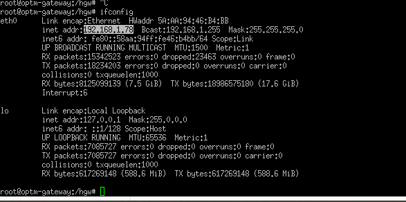
Retrieve IP Address with PuTTY:
- Use PuTTY to connect to the device. Enter the command "ifconfig" in the terminal to obtain the IP address.
- Refer to ifconfig.png for a visual reference.
-
Access the Web UI Page:
- Open a web browser and enter the obtained IP address in the address bar, then press "Enter" to access the Web UI page.
-
Tuner Configuration:
- The Web UI provides two tuner instance configuration tables for user selection, as shown in TunerConfiguration.png.
-
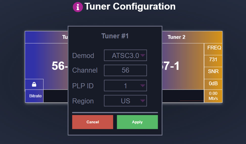
Click on a tuner table to open the tuner options menu, where users can choose settings based on
their requirements. The available options include:
- Demod
- Channel
- PlpId
- Region
Refer to UserTunerOption.png for details on tuner configuration options.
-
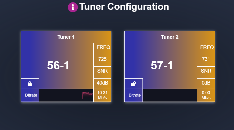
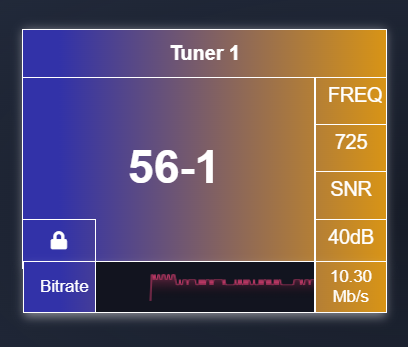
Applying Configuration:
- After configuring the desired tuner options, click "Apply" to initiate channel/service tuning.
- Once a channel/service lock is achieved, the Bitrate changes will become visible to the user.
-
Refer to Tuner1_Active.png to view the tuner in operation.
-
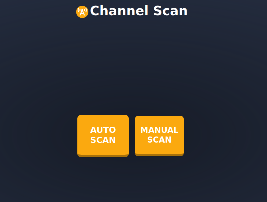
Channel Scan configuration:
- In the Web UI, users have options for channel scanning, allowing the detection and collection of available channels within a specified range.
- The Channel Scan feature includes two modes: Auto Scanning and Manual Scanning. For visual reference, see ChannelScan.png.
-
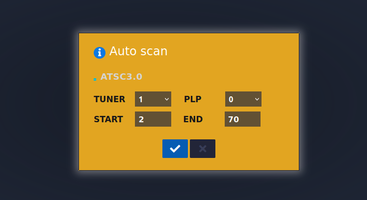
Auto Scanning
- Overview: Auto scanning automatically scans and collects services across a predefined channel range.
- Default Range: The default Start and End channels are set from channel 2 to channel 70, covering the full spectrum of available channels.
- Functionality: Based on the specified channel range, the frequency will vary as the system scans. Channels within this range are identified and locked if available, ensuring comprehensive coverage of all possible services.
- Reference Image: See AutoScan.png for an example of the Auto Scanning interface.
-
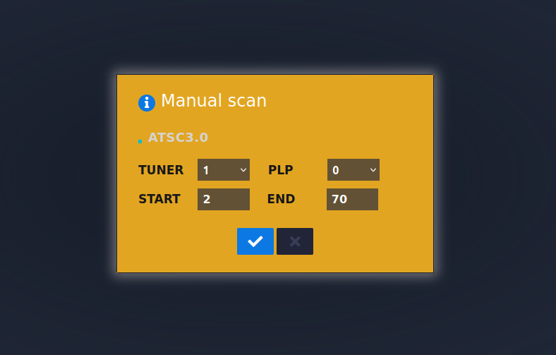
Manual Scanning:
- Overview: Manual scanning allows users to define a specific range for targeted scanning, giving control over the Start and End channel values.
- Configurable Range: Users can set a custom range from channel 2 to channel 70.
- Functionality: This scanning mode limits the search to the user-defined channel values, helping to focus the scan on a narrower range if needed. Only channels within this specified range will be detected and locked, optimizing the process based on user needs.
- Reference Image: See ManualScan.png for an example of the Manual Scanning interface.